My 20m/40m NVIS Antenna
Everything listed below, all the parts and processes contained herein, is just how I built my own 20m and 40m Near Vertical Incidence Skywave (NVIS) antenna. The original antenna was used during the Texas QSO Party site hosted by W5SH.org.
I made my own copy of this antenna; but it’s just that, a copy! I don’t know yet if it will work as well as the original one on which it’s modeled. Some final tuning may be required.
The antenna was raised to a height of 16 feet using four army-surplus camouflage net support poles.
At our TQP site we did not guy the antenna other than using the guy-lines that anchored the antenna elements. Feel free to guy your mast as you see fit.
The Parts List
One 1 ½” PVC “Y” fitting
Two 1 ½” PVC plugsOne 4” piece of 1 ½” PVC pipe
PVC glue/cement
Two ¼” – 20 x 1 ½” brass round-head machine screws
Two ¼” – 20 brass nuts
Two ¼” brass split washers
Two ¼” – 20 brass wingnuts
One chassis-mount SO-239 connector
Four #6 brass round-head machine screws
Four #6 brass split washers
Four #6 brass nuts
Two lengths ~10” #10 AWG wire in two colors (Red/Black)
Three ring terminals for #10 AWG wire
Four ring terminals for mounting to ¼” studs
~95 feet of #14 AWG stranded wire
~50 feet of 550 cord (also called Paracord)
Four egg / dogbone type insulatorsFour tent line tensioners
Four tent pegs
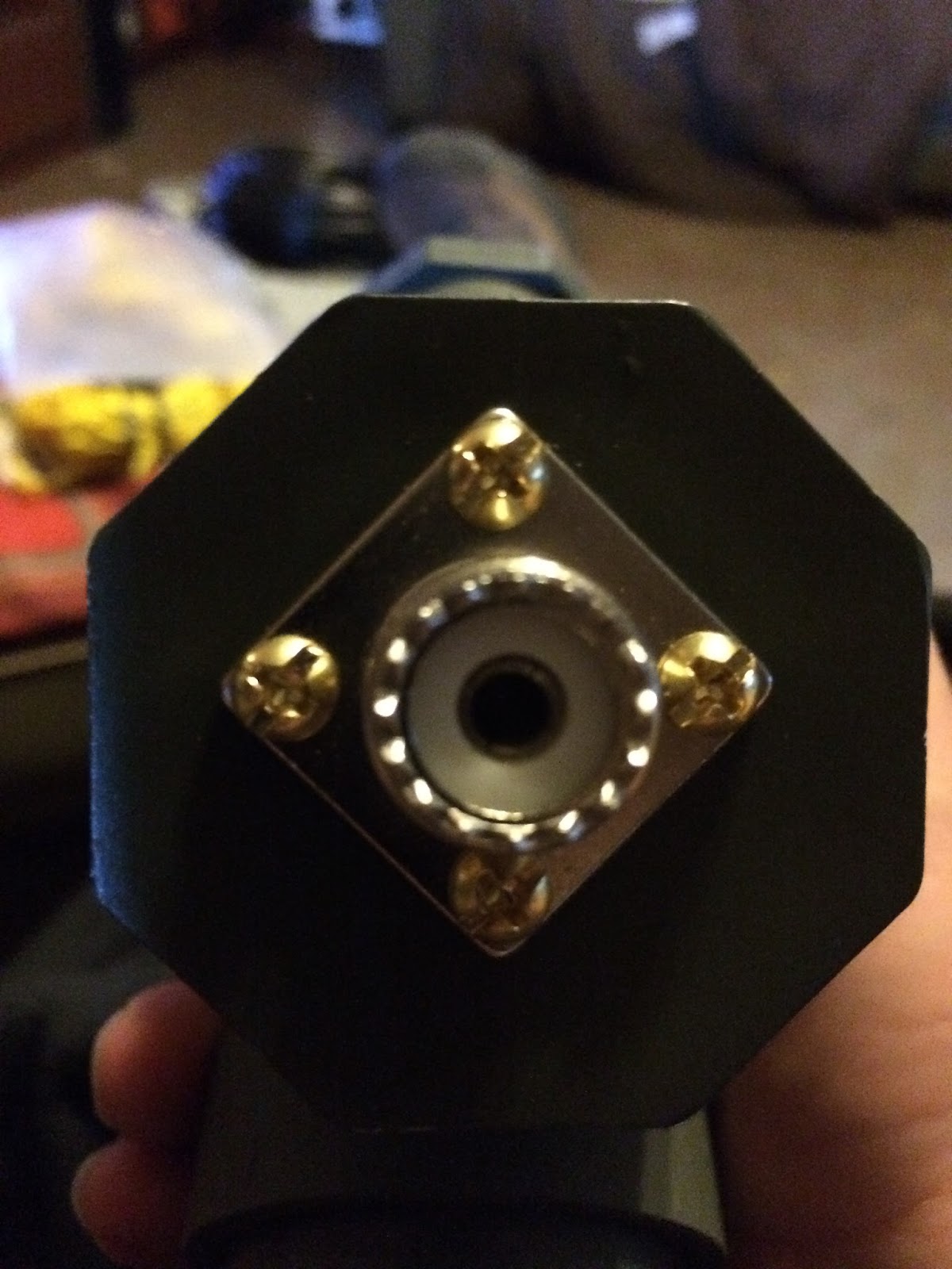
The Feed Point
I started with the easiest part, the feed point. It’s made with PVC fittings, the screws, two scrap pieces of #10 AWG wire and the SO-239 connector.
Take one of the PVC plugs and mark the center. Drill a ¾” hole for the chassis-mount SO-239 connector. Mark the locations for the small holes to mount the connector and drill them out. I then soldered one of the pieces of #10 wire to the center pin of the connector and a ring terminal on the other end. Solder a ring terminal on one end of the other piece of #10 wire. Mount the SO-239 to the PVC plug using the #6 brass screws, split washers and nuts. Onto one of these mounting screws you’ll need to attach the wire with the ring terminal. You can then glue the plug to the angle end of the PVC “Y” fitting as in the picture below.
As you hold the PVC “Y” with the SO-239 pointing down, you should have two wires poking out of the top. You can trim these two wires so that about 1 ½” is sticking out and solder ring terminals onto them.
Take the other PVC plug and drill two ¼” holes for the ¼” – 20 brass machine screws. I used the wingnuts to space the holes for the studs so that I can tighten the wingnuts without them touching each other.
One thing I forgot to mention and you can see from the pictures of the feed point is that I painted the PVC pieces OD green and coated with polyurethane. The top face of the PVC plug I painted half blue and half red. That’s just a personal thing I did. Painting is totally un-necessary. I just did it to make it look pretty.
Back to the PVC plug. Run the ¼” – 20 x 1½” brass machine screws up through the ring terminals on the wires and through the bottom of the plug. I needed to cut the ring terminals and open them up to fit around the machine screws. Fasten the screws with split washers and nuts. The plug should look like the picture below when finished. It can then be glued onto the PVC “Y”.

The last part of the feed point is to cut a 4” piece of 1 ½” PVC pipe and glue it onto the bottom of the “Y” fitting. The reason for using 1½” PVC is that it mates perfectly to US Army surplus camouflage net support poles, the standard antenna mast for most homebrew ham projects. Your finished feed point should look like the picture below.

The Antenna Elements
In theory each leg of the 20m dipole side of the antenna should be 16’ 5” if you assume the following formula:
234 / 14.250 MHz = 16.4210’
= 16 + (.4210 x 12)
= 16’ 5”
The measurements taken from the 20m legs for the one I have were 15’ 11⅞” and 15’ 10½” so just under 16’ but I’m OK with that because I know it works and works VERY well!
The same holds true for 40m:
234 / 7.212 MHz = 32.4459’
= 32 + (.4459 x 12)
= 32’ 5 5/16”
Again, you can tune yours for whatever you wish but the 40m legs on mine were 31’ 11½” and 31’ 8”. Not perfectly resonant at those two frequencies (the mathematical middle of the 20m and 40m voice bands); but my tuner will have no problem dialing them in. Anyway, back to construction.
So you’ll need to measure four pieces of #14 AWG wire: two for 20m and two for 40m. Solder ring terminals onto ONE end of each wire. On one of the 20m legs and 40m legs I wrapped a few turns of red electrical tape on the other two legs I wrapped a few turns of blue electrical tape. This way I can pair them up properly onto feed point.


Now you see why I painted the top of the PVC plug on the feed point.

Insulators and Guy-Lines
The attaching of the guy-lines and insulators is pretty straightforward. For each dipole leg I ran enough of the wire to leave 3” tail on the other side of each insulator. I used two small zip ties to form a loop holding each insulator in place. For neatness you could put a piece of heat-shrink tubing over the tail and zip ties. That’s up to the builder.

For the guy-lines I bought a 100’ package of high visibility 550-cord. Normally I choose something a little more “tactical”; but in this particular case I’m more concerned with safety and people not tearing down my antenna if they walk underneath it.
The guy-lines were measured to be the following lengths:
20m #1: 8’ 9½” 40m #1: 14’ 9”
20m #2: 9’ 3” 40m #2: 14’ 6”
About 3” of 550-cord was passed through the insulators and knots tied holding the insulators in place. Onto the end of each line I also tied a tent-line tensioner to snug the lines up once the antenna has been raised.

I haven’t decided yet if I’ll run a separate set of guy-lines for the mast. I guess that will depend on the conditions at the time I set it up. When it was used for the TQP the wind was light enough where no other guy-lines were needed.
Conclusion
This was my first real attempt at building my own antenna and I think it turned out pretty good. The design is compact enough to fit into a 1 gallon zip-top bag. The construction was simple using components cheaply and readily available.
NVIS also provides an excellent intermediate range communications option between UHF/VHF and traditional long-haul HF bands. During the Texas QSO Party not only was I able to work contacts within my own county but surrounding counties as well and even a couple stations farther out like Kentucky and Arizona all from western Fort Worth, Texas.
I hope my shameless copy of this antenna design will work well for you.
A special thanks goes out to Bill Boyer, KF5FEI, for letting me borrow his antenna during Texas QSO Party weekend and letting me blatantly copy his design!
No comments:
Post a Comment